Reading the electrical synoptic
Find the sources
Locate the two engine-driven generators, APU generator and any connected external power. Check whether the expected source is shown as available.
Read the figures
Read voltage and frequency where displayed.
Look for plausible voltage and frequency where shown. Do not interpret an isolated figure as proof that every downstream bus is powered.
Trace the path
FSS: green line means voltage sensed; white means not sensed.
Follow the associated lines through the system. FSS describes green electrical flow lines as voltage sensed and white as no voltage sensed.
Check AC and DC
Identify the AC buses and transformer rectifiers supplying DC. Compare their indications with the source and battery state.
Battery and essential buses
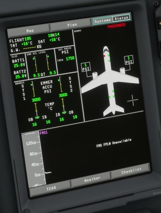
Read battery voltage and temperature on ELEC. If a battery is discharging, check CAS for BATT DISCHARGING; FSS documents voltage and temperature on ELEC, not a separate charge-state indication.
Recheck after a change
After a change, inspect sources and supplied buses again.
After an engine start or ground-power removal, scan the sources and bus lines again rather than assuming the transfer went as planned.
An overhead selection expresses what you requested. The synoptic and CAS show what the simulated electrical system reports in response.
The FSS ELEC page shows an external-power icon only when that source is connected and available. The APU icon appears after the APU becomes available: FSS gives three seconds after 95% RPM. A green APU icon means the generator is available and selected; a white icon means it is available but the generator button is out. Check the flow lines as well to see which buses have voltage.
The electrical buses and TRU indications remain on the page. FSS says each TRU icon and its outputs are always displayed; green means the unit is available with its selector in AUTO, white means it is available with the selector OFF. Battery voltage and temperature are also shown. A green electrical line means voltage is sensed; white means it is not. Read those lines alongside the source and bus labels. The RAT symbol appears only when the RAT is deployed. FSS ELEC synoptic [93].