New wings and a taller undercarriage
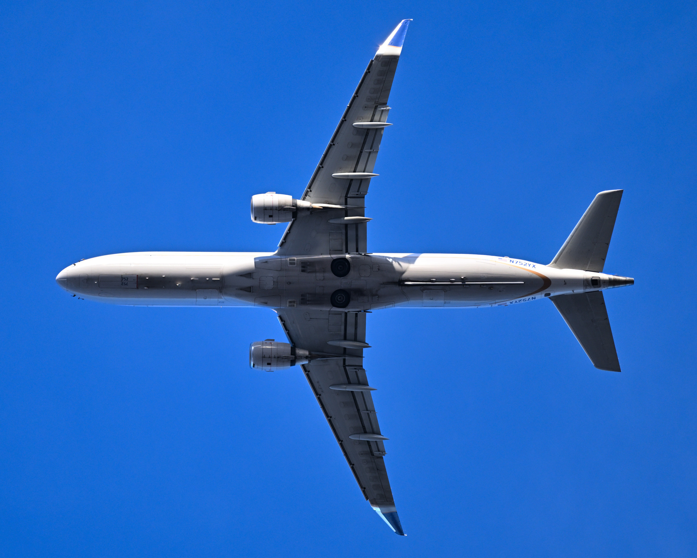
The E2 airframe When the E195-E2 rolled out on 7 March 2017, the extra length was immediately apparent. Three additional seat rows had been incorporated relative to the first-generation E195, and Embraer now offered a maximum single-class arrangement of 146 seats. The aircraft received its own wing, extending beyond the span of the E190-E2. Elsewhere, the aerodynamic surfaces became smaller. Embraer said that the new flight-control system had allowed a twenty per cent reduction in empennage area, reducing weight and drag. The programme’s control engineers could influence the size of the tail as well as the movement of its surfaces. The largest E2 combined a longer cabin and greater wing span with this reduction at the rear of the aircraft, altering several proportions of the original E195 at once.
The E190-E2 retained a fuselage length of about 36.24 metres, almost identical to the E190, while its span reached 33.72 metres. The E195-E2 grew to 41.60 metres in length and 35.12 metres in span. The two E2 aircraft consequently no longer shared a single span as the original E190 and E195 had done. Their formal model names became ERJ 190-300 and ERJ 190-400, within the existing ERJ 190 certification family.
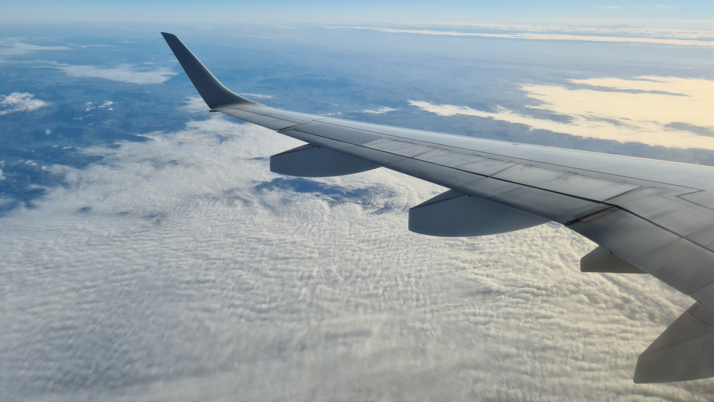
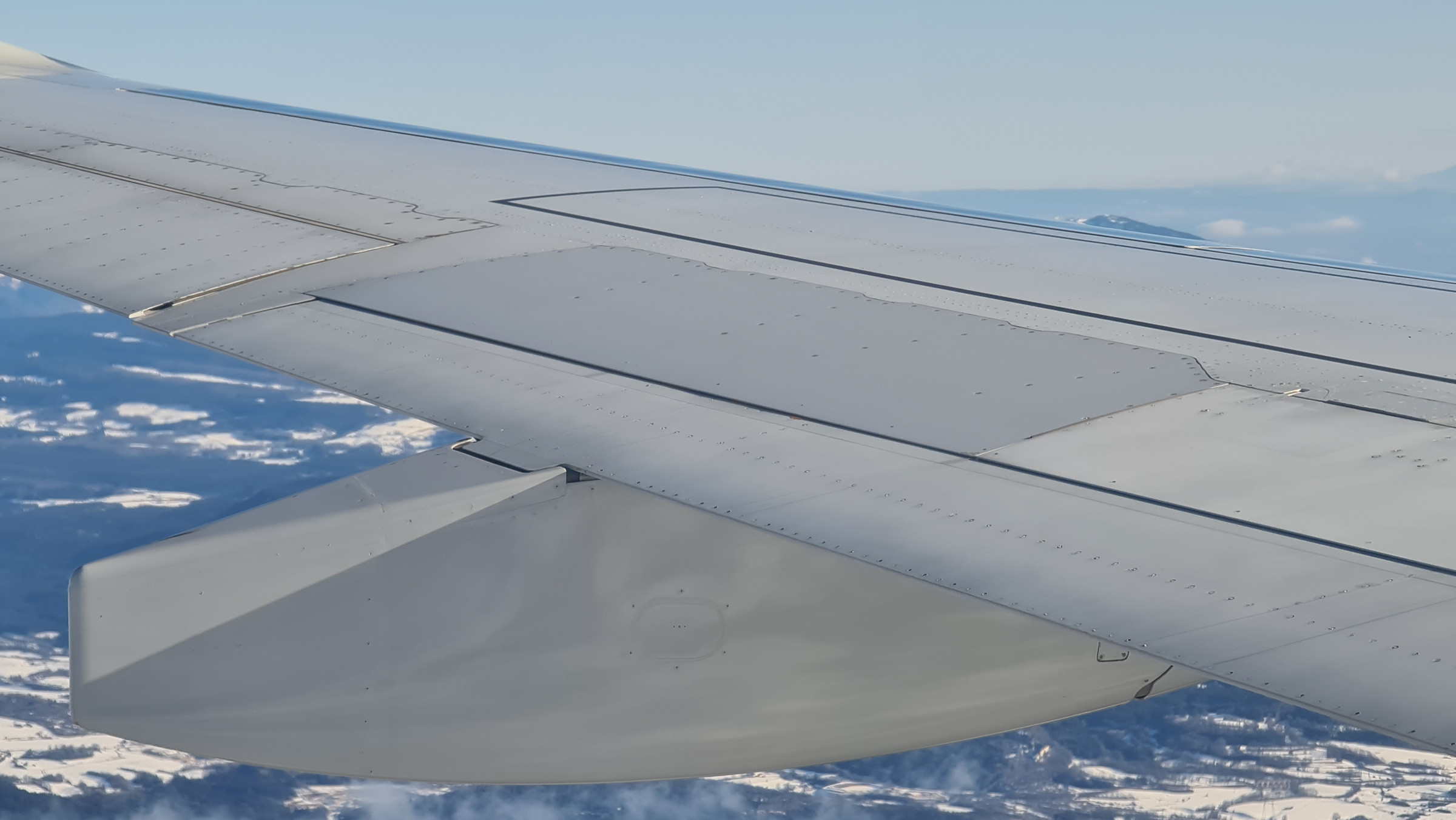
Embraer coupled the slender new wings with single-slotted flaps and full fly-by-wire control. The flight-control change removed mechanical cables, pulleys and associated mechanisms from parts of the control system, reducing their contribution to weight. More consequentially, control laws and flight-envelope protections shaped the aerodynamic loads that the structure had to withstand. Embraer could design lighter structural solutions around those controlled loads. The wing, control system and structure were therefore developed together: the wing provided the aerodynamic performance, while the electronic controls helped manage the forces generated in flight. The company carried these relationships through the E2 design, seeking reductions in fuel consumption from the airframe as well as from the engine. A change within the control computers could have a physical consequence in the quantity of structure required elsewhere on the aircraft.44
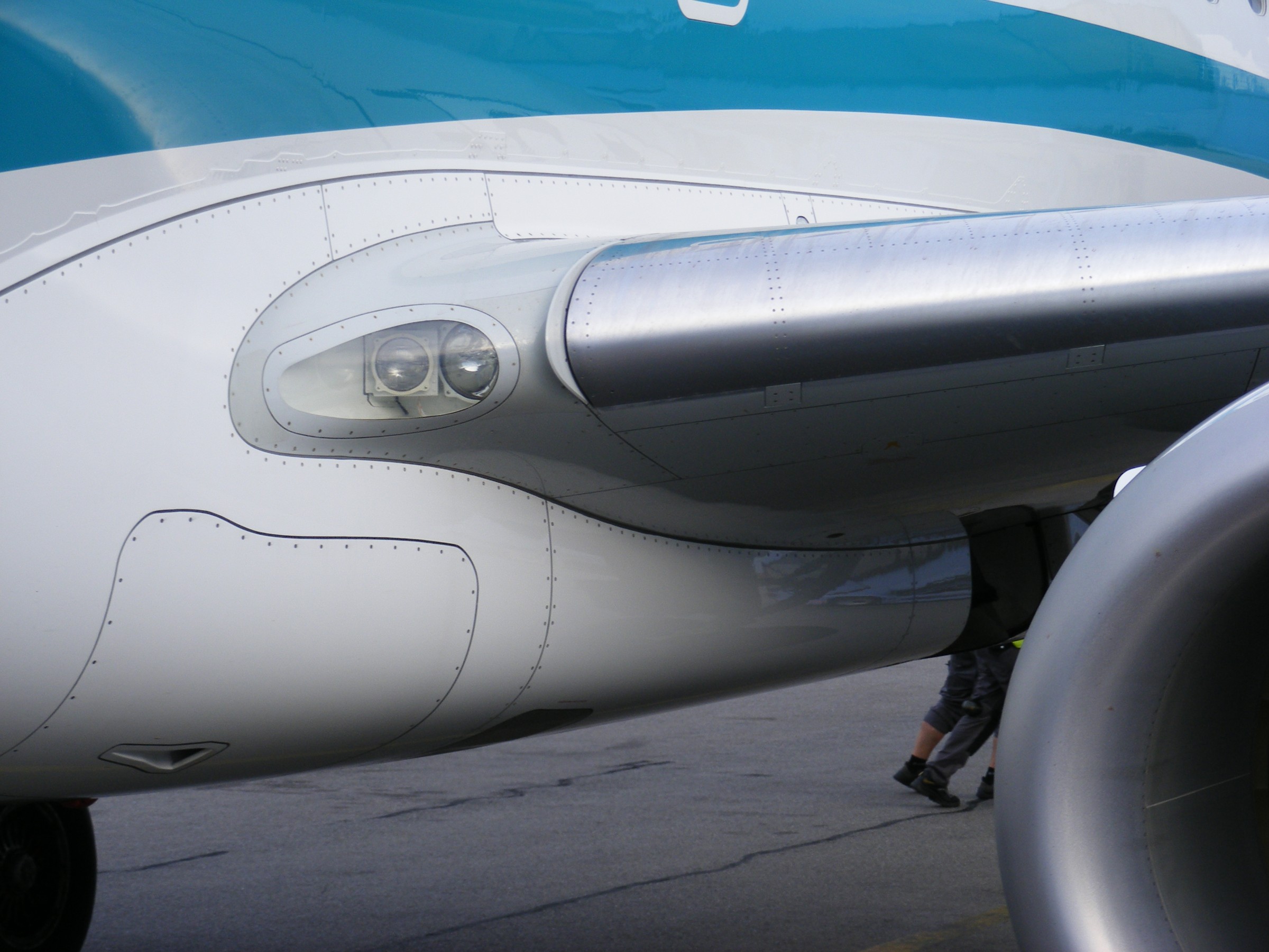
The propulsion installation imposed a more visible requirement beneath the wing. In its May 2013 contract announcement, Moog described an extended main landing gear intended to provide clearance for the new, higher-bypass engines. The E2’s larger fan had to fit below a low wing and remain sufficiently clear of the pavement. Raising the aircraft also changed its ground geometry. Moog’s package linked this new airframe to an integrated three-axis primary flight-control system, combining the supplier’s computers, software, actuators and control electronics. The engine installation, landing gear and flight controls thus appeared together in the early definition of the aircraft, before the first prototype’s structure was assembled. Extending the undercarriage was one of the changes needed to accommodate the new propulsion system within the retained passenger-aircraft architecture.45
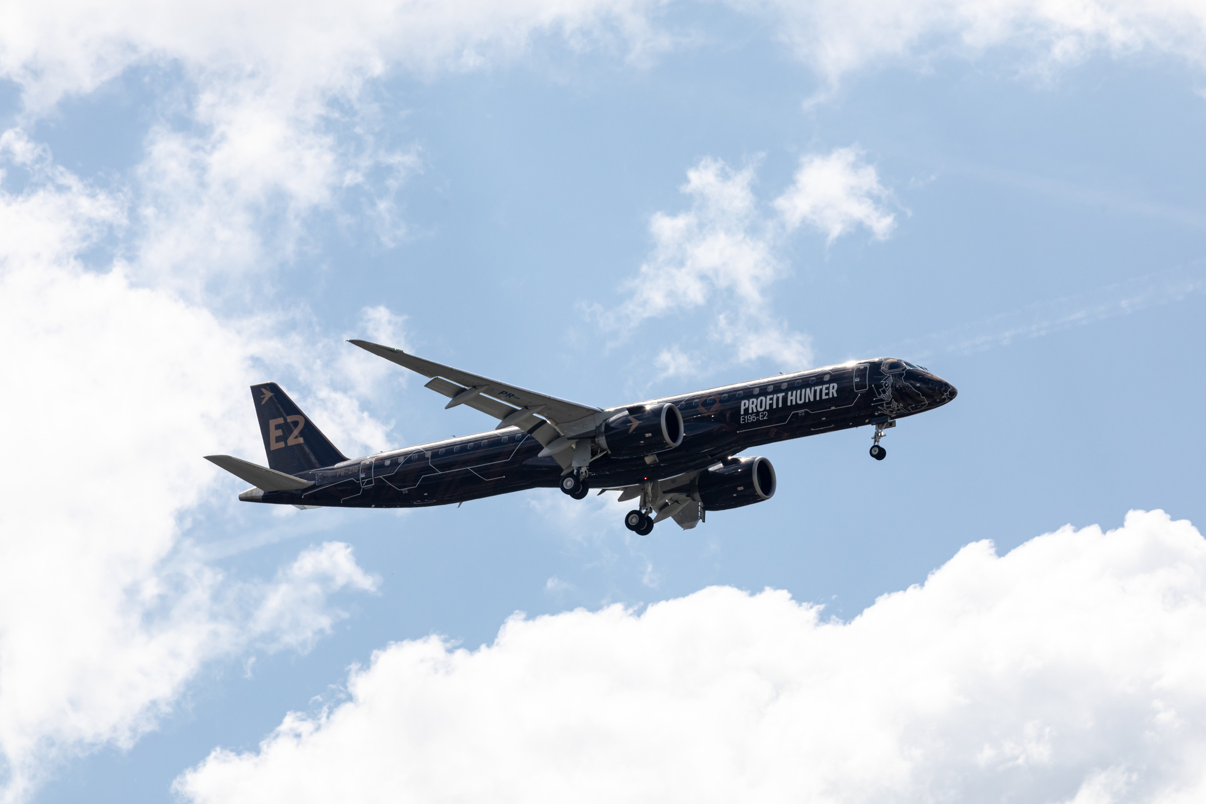
The finished design used a trailing-arm main undercarriage. Both main and nose gears increased the fuselage’s ground clearance, and additional doors enclosed the main gear when retracted. These changes accompanied the altered systems and control architecture documented in the Canadian operational evaluation of the E2.46
For nosewheel steering, Embraer retained an existing supplier and a line of development from the first generation. In May 2014, Liebherr-Aerospace Lindenberg received the contract for the steering control module. Its design would be based on the module already developed for the E1, adapting established equipment to the new aircraft. Liebherr had already secured the high-lift and air-management systems, so the steering contract extended its involvement from the wing and cabin environment to the aircraft’s movement on the ground. The main landing gear could change in height and configuration while the steering module drew on equipment that had accumulated experience with the earlier E-Jets.<sup class="citation"><a href="/sources/#source-47">47</a></sup> The E2’s increased span still fitted within the airport-planning Code C span band, extending from twenty-four metres to below thirty-six metres. Embraer’s planning manual assigns both the ERJ 190-300 and -400 a 3C reference code. The longer E195-E2 nevertheless needed its own turning and clearance calculations. The manual plots the paths of the wheels, nose, tail and wingtips at different steering angles, using a maximum nosewheel angle of seventy-six degrees each side for minimum-turn calculations. These are theoretical no-slip paths; an actual aircraft can require more pavement. The growing wing and fuselage therefore reached into airport design through specific swept areas and wheel positions. A stand or turning bay suitable for an earlier aircraft still had to accommodate the new model’s complete outline as it moved.<sup class="citation"><a href="/sources/#source-48">48</a></sup> Ground handling had been part of the family’s engineering from the beginning. In the E190’s servicing arrangement, baggage loaders reach the forward and aft holds while separate vehicles serve the galleys, fuel connection, drinking-water system and lavatory. Embraer’s model turnaround allows the two baggage holds to be worked in parallel and the forward and rear galleys to be serviced simultaneously. Passengers use the forward door in that model, matching a stand equipped with a single boarding bridge. The same airframe had to accept stairs, loaders and servicing equipment positioned close to its wings and engines. The arrangement gave airlines several tasks they could perform at once, provided the airport supplied the people and equipment around the aircraft.49